McIntosh MC275 Owner's Manual
Browse online or download Owner's Manual for Supplementary music equipment McIntosh MC275. McIntosh MC275 Owner`s manual User Manual
- Page / 20
- Table of contents
- BOOKMARKS
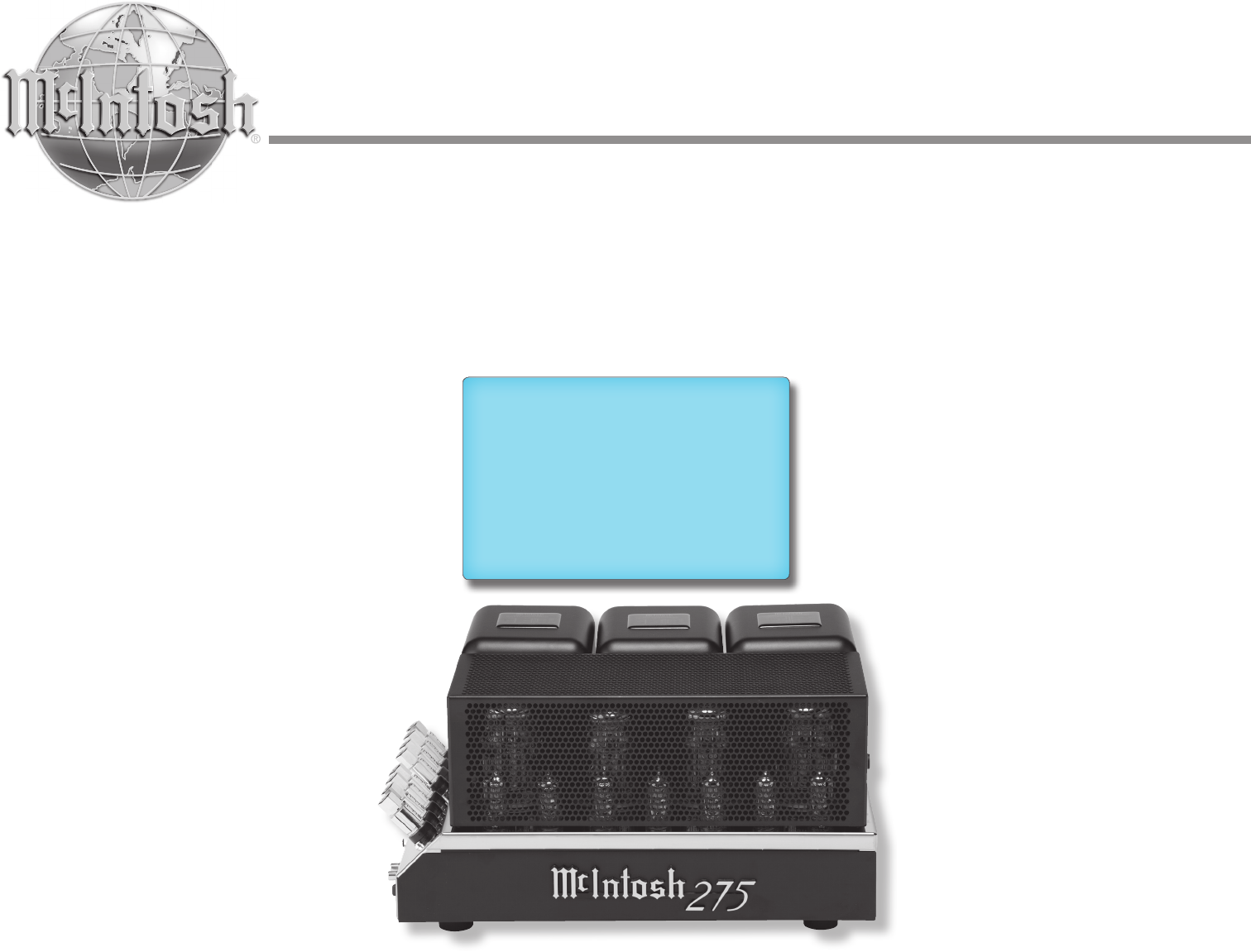
- Tube Power Amplier 1
- Owner’s Manual 1
- IMPORTANT SAFETY 2
- INSTRUCTIONS! 2
- IMPORTANT! 3
- MANUAL FOR INSTRUCTIONS 4
- Ventilation 5
- Introduction 7
- Performance Features 7
- Dimensions 8
- Output Terminals 10
- Figure 4 11
- Figure 5 11
- Figure F 13
- Figure H 13
- Handcrafted in USA with US 14
- How to Operate 15
- Specications 18
- Packing Instructions 19
- McIntosh Part No. 04132700 20
Summary of Contents
McIntosh Laboratory, Inc. 2 Chambers Street Binghamton, New York 13903-2699 Phone: 607-723-3512 www.mcintoshlabs.comMC275Tube Power AmplierO
10Caution: Do not connect the AC Power Cord to the MC275 Right Side Panel until after the Loud-speaker Connections are made. Failure to observe this c
11If the Loudspeaker’s impedance is in-between the available connections, use the nearest lower imped-ance connection. Refer to “General Information”
12Caution: Do not connect the AC Power Cord to the MC275 Right Side Panel until after the Loud-speaker Connections are made. Failure to observe this c
1313. In a similar manner, connect the other Jumper Bar between the two (+) Positive 16Ω Output Termi-nals for connecting a 8Ω (ohm) Loudspeaker (or b
14Handcrafted in USA with USand Imported PartsRight Side Switch, Left Side Switches and IndicatorsStandby Power On IndicatorAUTO OFF Switches the Powe
15How to OperateHow to OperateWhen there is a Power Control Connec-tion between the MC275 and a Preamplifier with Power Save Circuitry, the AUTO OFF S
17Photos
18Overall DimensionsWidth is 21-1/2 inches (54.6cm) including CablesHeight is 8-1/2 inches (21.6cm) including feetDepth is 12 inches (30.5cm)Weight67
19Packing InstructionsPacking InstructionsQuantity Part Number Description1 034529 Shipping carton1 034526 Foam Pad Top2 034527 Foam Pad Botto
2The lightning ash with arrowhead, within an equilateral triangle, is intended to alert the user to the presence of uninsulated “dangerous voltage” w
The continuous improvement of its products is the policy of McIntosh Laboratory Incorporated who reserve the right to improve design without notice.Pr
3IMPORTANT!INSTRUCTIONS FOR REMOVALOF FOAM INSERT OVER THEVACUUM TUBES PRIOR TOCONNECTING THE A.C. POWERSUPPLY CORD, START ON THENEXT PAGE.
4Unpacking the MC275Caution: To prevent damage to the MC275 Tubes during shipping, there is a special foam insert surrounding the Tubes of the Power A
5Adequate ventilation extends the trouble free life of the MC275. Always allow air to flow through the ventilation holes on the bottom of the amplifie
61. For additional connection information, refer to the owner’s manual(s) for any component(s) connected to the MC275.2. The MC275 mutes the speaker o
7General Information, Cable Information, Introduction and Performance Features XLR ConnectorsBelow is the Pin configuration for the XLR Balanced Input
8DimensionsThe following dimensions can assist in determining the best location for your MC275.Dimensions8-1/2"21.6cmFront View of the MC275Top V
9Handcrafted in USA with USand Imported PartsLeft Side Connections, Indicator and Switch; Right Side Connection, Fuse Holder and SwitchConnect the MC2
Related products and manuals for Supplementary music equipment McIntosh MC275
 (44 pages)
© 2020, manymanuals.com. All rights reserved. | 1.584 s |
 Manymanuals.com
 Manymanuals.de
 Manymanuals.fr
 Manymanuals.it
 Manymanuals.pl
 Manymanuals.cz
 Manymanuals.es
 Manymanuals-pt.com
Comments to this Manuals